Explore This Guide
Jump directly to any section of this article.
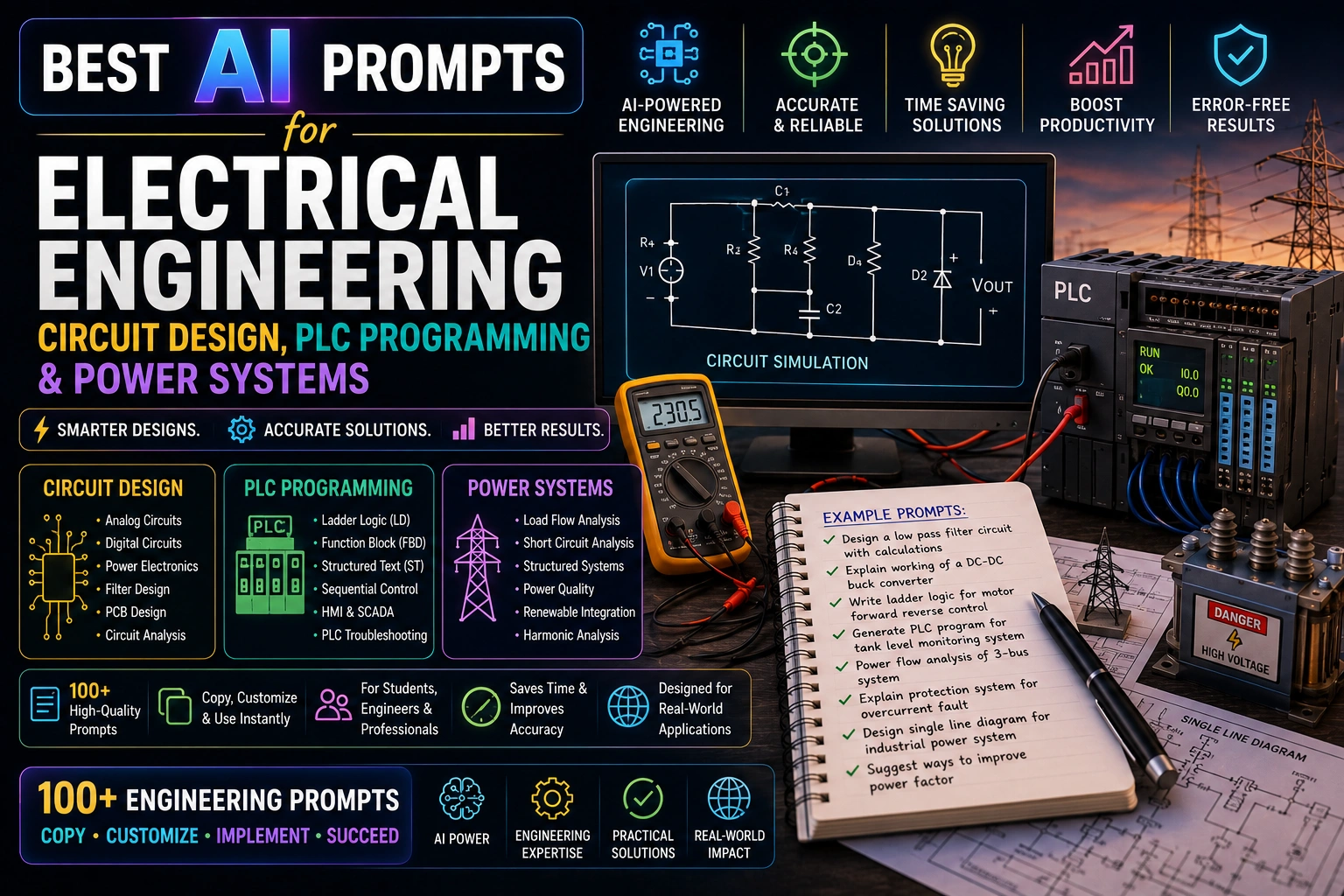
AI Prompts for Circuit Design, PLC Logic & Power Systems
Select a category or browse all electrical engineering prompts below
1. Circuit Component Selection Overview
CIRCUIT DESIGNCompare component options for a circuit function.
Act as a circuit design assistant. Compare component options
for implementing [function, e.g. voltage regulation, signal
filtering] in a circuit operating at [voltage/current/frequency].
Include cost, efficiency, and thermal considerations for each
option to verify with datasheets.
Act as a circuit design assistant. Compare component options
for implementing [function, e.g. voltage regulation, signal
filtering] in a circuit operating at [voltage/current/frequency].
Include cost, efficiency, and thermal considerations for each
option to verify with datasheets.
2. Op-Amp Circuit Topology Comparison
CIRCUIT DESIGNCompare op-amp configurations for a signal processing need.
Compare op-amp circuit topologies (inverting, non-inverting,
differential, instrumentation) for [application, e.g. amplifying
a sensor signal]. Include gain equations, input impedance
considerations, and typical use cases for each topology.
Compare op-amp circuit topologies (inverting, non-inverting,
differential, instrumentation) for [application, e.g. amplifying
a sensor signal]. Include gain equations, input impedance
considerations, and typical use cases for each topology.
3. Power Supply Topology Selector
CIRCUIT DESIGNCompare power supply topologies for a design.
Compare power supply topologies (linear regulator, buck
converter, boost converter, flyback) for converting
[input voltage] to [output voltage] at [current requirement].
Include efficiency, noise, and complexity trade-offs.
Compare power supply topologies (linear regulator, buck
converter, boost converter, flyback) for converting
[input voltage] to [output voltage] at [current requirement].
Include efficiency, noise, and complexity trade-offs.
4. PCB Layout Review Checklist
CIRCUIT DESIGNReview a PCB layout for common design issues.
Create a PCB layout review checklist for a board containing
[describe circuit, e.g. switching power supply, high-speed
digital lines]. Include trace width/current capacity, ground
plane strategy, decoupling capacitor placement, and EMI
mitigation items to verify.
Create a PCB layout review checklist for a board containing
[describe circuit, e.g. switching power supply, high-speed
digital lines]. Include trace width/current capacity, ground
plane strategy, decoupling capacitor placement, and EMI
mitigation items to verify.
5. Filter Design Overview
CIRCUIT DESIGNCompare filter types for a signal processing requirement.
Compare filter types (Butterworth, Chebyshev, Bessel) for
[application, e.g. removing noise above X Hz from a sensor
signal]. Include passband ripple, roll-off steepness, and
phase response trade-offs relevant to the application.
Compare filter types (Butterworth, Chebyshev, Bessel) for
[application, e.g. removing noise above X Hz from a sensor
signal]. Include passband ripple, roll-off steepness, and
phase response trade-offs relevant to the application.
6. Microcontroller Selection Comparison
CIRCUIT DESIGNCompare microcontroller options for an embedded design.
Compare microcontroller options ([MCU family 1], [MCU family 2],
[MCU family 3]) for a project requiring
[peripherals/requirements, e.g. low power, multiple ADC channels,
wireless connectivity]. Include cost, power consumption, and
ecosystem/tooling trade-offs.
Compare microcontroller options ([MCU family 1], [MCU family 2],
[MCU family 3]) for a project requiring
[peripherals/requirements, e.g. low power, multiple ADC channels,
wireless connectivity]. Include cost, power consumption, and
ecosystem/tooling trade-offs.
7. Circuit Protection Scheme Overview
CIRCUIT DESIGNOrganize protection component selection for a circuit.
Summarize circuit protection strategy for a [circuit description]
against [threats, e.g. overcurrent, ESD, reverse polarity].
Include fuse/breaker sizing considerations, TVS diode selection
basics, and where protection should be placed in the circuit.
Summarize circuit protection strategy for a [circuit description]
against [threats, e.g. overcurrent, ESD, reverse polarity].
Include fuse/breaker sizing considerations, TVS diode selection
basics, and where protection should be placed in the circuit.
8. Battery Management Circuit Concept
CIRCUIT DESIGNOutline a battery management approach for a battery-powered device.
Outline a battery management circuit concept for a
[battery chemistry, e.g. Li-ion] pack of [voltage/capacity]
powering [device type]. Include charging protection, cell
balancing considerations, and low-voltage cutoff strategy.
Outline a battery management circuit concept for a
[battery chemistry, e.g. Li-ion] pack of [voltage/capacity]
powering [device type]. Include charging protection, cell
balancing considerations, and low-voltage cutoff strategy.
9. Signal Integrity Review Notes
CIRCUIT DESIGNSummarize signal integrity considerations for a high-speed design.
Summarize signal integrity considerations for a
[signal type, e.g. differential pair, clock line] running at
[frequency/data rate] over [trace length]. Include impedance
matching, termination strategy, and crosstalk mitigation to
verify with simulation.
Summarize signal integrity considerations for a
[signal type, e.g. differential pair, clock line] running at
[frequency/data rate] over [trace length]. Include impedance
matching, termination strategy, and crosstalk mitigation to
verify with simulation.
10. Schematic Design Review Checklist (Incl. Hardware Security)
CIRCUIT DESIGNA schematic review checklist that also covers the EMI and hardware-security checks now expected on connected designs.
Create a schematic design review checklist for a
[circuit description]. Include power supply decoupling, pull-up/
pull-down resistor verification, connector pinout checks, and
common errors to look for based on the design scope. If the
design uses wide-bandgap switching devices (GaN/SiC), add EMI
layout checks for the higher switching frequencies, and if the
board is network-connected, add a hardware-security pass
(secure boot/root of trust placement, debug port lockdown,
tamper-evidence considerations).
Create a schematic design review checklist for a
[circuit description]. Include power supply decoupling, pull-up/
pull-down resistor verification, connector pinout checks, and
common errors to look for based on the design scope. If the
design uses wide-bandgap switching devices (GaN/SiC), add EMI
layout checks for the higher switching frequencies, and if the
board is network-connected, add a hardware-security pass
(secure boot/root of trust placement, debug port lockdown,
tamper-evidence considerations).
11. PLC I/O List Organizer (Network-Exposure Flagged)
PLC PROGRAMMINGAn I/O list that also flags which points are remotely/network accessible, since that's now a security review item.
Create a PLC I/O list template for a [process/machine
description]. Include tag name, description, I/O type
(digital/analog input/output), address, and associated
field device for each point, plus a column flagging which
points are reachable via a remote/network-connected device
(wireless sensor, remote I/O rack, VFD on Ethernet) so the
OT security review knows exactly which points to include in
network segmentation planning.
Create a PLC I/O list template for a [process/machine
description]. Include tag name, description, I/O type
(digital/analog input/output), address, and associated
field device for each point, plus a column flagging which
points are reachable via a remote/network-connected device
(wireless sensor, remote I/O rack, VFD on Ethernet) so the
OT security review knows exactly which points to include in
network segmentation planning.
12. Ladder Logic Sequence Draft (Edge-Preprocessing Aware)
PLC PROGRAMMINGA ladder logic sequence description that also flags which steps could be pre-processed at the edge instead of on the PLC scan.
Draft a ladder logic sequence description for
[process description, e.g. a conveyor start/stop sequence with
interlocks]. Include the rungs in plain-language logic order,
interlock conditions, and fault handling, for the controls
programmer to implement, and note any steps involving heavy
sensor-data processing (vision, vibration analysis) that would
be better handled by an edge-computing device feeding a clean
digital result back to the PLC, rather than burdening the PLC
scan cycle directly.
Draft a ladder logic sequence description for
[process description, e.g. a conveyor start/stop sequence with
interlocks]. Include the rungs in plain-language logic order,
interlock conditions, and fault handling, for the controls
programmer to implement, and note any steps involving heavy
sensor-data processing (vision, vibration analysis) that would
be better handled by an edge-computing device feeding a clean
digital result back to the PLC, rather than burdening the PLC
scan cycle directly.
13. State Machine Design with Digital-Twin Validation Step
PLC PROGRAMMINGStructure a state machine and note which transitions should be validated in simulation before touching real equipment.
Design a state machine for [process description, e.g. a fill-
and-cap packaging line]. Include each state, the transition
conditions between states, and fault/reset states, presented
as a table or state diagram description, and flag which
transitions (especially fault-recovery and edge-case paths)
should be validated against a digital-twin or simulation model
before being commissioned on the physical line.
Design a state machine for [process description, e.g. a fill-
and-cap packaging line]. Include each state, the transition
conditions between states, and fault/reset states, presented
as a table or state diagram description, and flag which
transitions (especially fault-recovery and edge-case paths)
should be validated against a digital-twin or simulation model
before being commissioned on the physical line.
14. Alarm & Fault Handling Logic (AI-Anomaly-Aware)
PLC PROGRAMMINGStandard alarm/fault logic, plus where an ML anomaly-detection layer could catch drift before a hard threshold trips.
Create an alarm and fault handling outline for
[machine/process description]. Include alarm conditions, severity
level, automatic response (e.g. stop, alert, continue), and
operator acknowledgment requirements for each alarm, and note
which alarms are good candidates for an added ML-based anomaly-
detection layer (catching gradual drift or unusual patterns)
running alongside the fixed-threshold alarms rather than
replacing them.
Create an alarm and fault handling outline for
[machine/process description]. Include alarm conditions, severity
level, automatic response (e.g. stop, alert, continue), and
operator acknowledgment requirements for each alarm, and note
which alarms are good candidates for an added ML-based anomaly-
detection layer (catching gradual drift or unusual patterns)
running alongside the fixed-threshold alarms rather than
replacing them.
15. HMI Screen Layout Concept (Secure Remote Access)
PLC PROGRAMMINGHMI layout plus the access-control considerations needed now that remote/cloud dashboard access is standard.
Draft an HMI screen layout concept for monitoring/controlling
[process description]. Include key values to display, control
buttons needed, alarm banner placement, and navigation to
related screens, following clear operator usability principles,
and note the access-control tiering needed if this HMI (or a
read-only version of it) will also be exposed to a remote/cloud
dashboard for off-site monitoring.
Draft an HMI screen layout concept for monitoring/controlling
[process description]. Include key values to display, control
buttons needed, alarm banner placement, and navigation to
related screens, following clear operator usability principles,
and note the access-control tiering needed if this HMI (or a
read-only version of it) will also be exposed to a remote/cloud
dashboard for off-site monitoring.
16. PID Control Loop Tuning Notes (Manual + AI Auto-Tune)
PLC PROGRAMMINGThe standard manual tuning approach, plus when an AI/ML auto-tuning tool is worth using instead.
Summarize a PID tuning approach for controlling
[process variable, e.g. temperature, flow, pressure] with
[process characteristics, e.g. slow-responding, fast-responding].
Include a starting method (Ziegler-Nichols or similar) and signs
of an over/under-tuned loop, and note when this loop is a good
candidate for an AI/ML-based auto-tuning tool (e.g. highly
nonlinear or frequently-changing process conditions) versus
when manual tuning is simpler and sufficient.
Summarize a PID tuning approach for controlling
[process variable, e.g. temperature, flow, pressure] with
[process characteristics, e.g. slow-responding, fast-responding].
Include a starting method (Ziegler-Nichols or similar) and signs
of an over/under-tuned loop, and note when this loop is a good
candidate for an AI/ML-based auto-tuning tool (e.g. highly
nonlinear or frequently-changing process conditions) versus
when manual tuning is simpler and sufficient.
17. Safety Interlock Logic Review (Cobot/Humanoid-Aware)
PLC PROGRAMMINGInterlock review updated for collaborative and increasingly autonomous robots working alongside people on the floor.
Review the safety interlock logic requirements for
[machine description, e.g. a press with a light curtain and
e-stop]. List the required interlock conditions, safety relay
or safety PLC considerations, and standard categories
(e.g. ISO 13849) to verify with a safety engineer, and if a
collaborative or autonomous mobile robot shares the workspace,
add the ISO/TS 15066 collaborative-safety interlocks and
speed/separation-monitoring considerations specific to that
robot's operating envelope.
Review the safety interlock logic requirements for
[machine description, e.g. a press with a light curtain and
e-stop]. List the required interlock conditions, safety relay
or safety PLC considerations, and standard categories
(e.g. ISO 13849) to verify with a safety engineer, and if a
collaborative or autonomous mobile robot shares the workspace,
add the ISO/TS 15066 collaborative-safety interlocks and
speed/separation-monitoring considerations specific to that
robot's operating envelope.
18. Communication Protocol Selection (Incl. TSN & OT Security)
PLC PROGRAMMINGProtocol comparison expanded to cover time-sensitive networking and the network-segmentation implications of each choice.
Compare industrial communication protocols (Modbus TCP,
EtherNet/IP, Profinet, OPC UA, and OPC UA over TSN for
time-critical motion/synchronization needs) for connecting
[devices, e.g. PLC to VFDs and sensors] on a
[network size/topology]. Include compatibility, speed, and
setup complexity trade-offs, plus the network-segmentation and
firewall implications of each protocol for an OT cybersecurity
review.
Compare industrial communication protocols (Modbus TCP,
EtherNet/IP, Profinet, OPC UA, and OPC UA over TSN for
time-critical motion/synchronization needs) for connecting
[devices, e.g. PLC to VFDs and sensors] on a
[network size/topology]. Include compatibility, speed, and
setup complexity trade-offs, plus the network-segmentation and
firewall implications of each protocol for an OT cybersecurity
review.
19. Recipe Management Structure Draft (Tamper-Checked)
PLC PROGRAMMINGRecipe management structure with an added integrity check, since recipe/setpoint tampering is a known OT attack vector.
Draft a recipe management structure for a [machine/process]
that runs multiple product variants: [list variants].
Include parameters that change per recipe, storage approach,
and validation checks before a recipe is loaded to the process,
and add an integrity/tamper-check step (checksum or signed
recipe file, change-log with operator ID) so an unauthorized
or accidental setpoint change is caught before it's loaded live.
Draft a recipe management structure for a [machine/process]
that runs multiple product variants: [list variants].
Include parameters that change per recipe, storage approach,
and validation checks before a recipe is loaded to the process,
and add an integrity/tamper-check step (checksum or signed
recipe file, change-log with operator ID) so an unauthorized
or accidental setpoint change is caught before it's loaded live.
20. PLC Program Documentation Template (Firmware/Patch Log)
PLC PROGRAMMINGStandard program documentation plus the firmware/patch tracking now expected for OT cybersecurity audits.
Create a documentation template for a completed PLC program
controlling [process description]. Include sections for program
overview, tag/variable list, logic description by routine, and
revision history for future maintainers, and add a firmware/
patch-level log for the PLC, HMI, and any networked field
devices so a security audit can quickly confirm what's running
and whether known vulnerabilities have been patched.
Create a documentation template for a completed PLC program
controlling [process description]. Include sections for program
overview, tag/variable list, logic description by routine, and
revision history for future maintainers, and add a firmware/
patch-level log for the PLC, HMI, and any networked field
devices so a security audit can quickly confirm what's running
and whether known vulnerabilities have been patched.
21. Load Calculation Summary (EV & Data-Center Growth Aware)
POWER SYSTEMSElectrical load calculations that build in headroom for the load growth utilities are now planning around.
Organize an electrical load calculation summary for a
[facility type] with [list major loads, e.g. HVAC, lighting,
process equipment]. Include demand factor considerations and
total connected vs. demand load, referencing NEC or applicable
code for final values, and add a forward-looking margin line
item for likely future load growth (EV charging buildout,
added compute/data-center capacity, electrification of
equipment currently running on gas) rather than sizing strictly
to today's connected load.
Organize an electrical load calculation summary for a
[facility type] with [list major loads, e.g. HVAC, lighting,
process equipment]. Include demand factor considerations and
total connected vs. demand load, referencing NEC or applicable
code for final values, and add a forward-looking margin line
item for likely future load growth (EV charging buildout,
added compute/data-center capacity, electrification of
equipment currently running on gas) rather than sizing strictly
to today's connected load.
22. Transformer Sizing Overview (DER/Renewable-Ready)
POWER SYSTEMSTransformer sizing that also flags what changes if solar, battery storage, or other DERs interconnect at this point.
Summarize transformer sizing considerations for serving
[load in kVA] at [voltage levels, e.g. 480V to 208Y/120V].
Include kVA rating margin, impedance considerations, and
cooling class options (ONAN, ONAF) to verify with the
manufacturer, and note what additional sizing/impedance
considerations apply if a distributed energy resource (rooftop
solar, battery energy storage) will interconnect at or near
this transformer.
Summarize transformer sizing considerations for serving
[load in kVA] at [voltage levels, e.g. 480V to 208Y/120V].
Include kVA rating margin, impedance considerations, and
cooling class options (ONAN, ONAF) to verify with the
manufacturer, and note what additional sizing/impedance
considerations apply if a distributed energy resource (rooftop
solar, battery energy storage) will interconnect at or near
this transformer.
23. Short Circuit Study Overview (Inverter-Based Resources)
POWER SYSTEMSShort circuit study inputs updated for how inverter-based solar/battery sources change fault current behavior.
Outline the inputs needed for a short circuit study on a
[facility type] electrical system with [utility service size]
service. Include source impedance, transformer impedance,
conductor data, and equipment interrupting rating checks
needed from the study, and if any inverter-based resources
(solar PV, battery storage) contribute fault current at this
site, note how their limited and short-duration fault
contribution differs from a traditional synchronous source and
why that needs separate modeling.
Outline the inputs needed for a short circuit study on a
[facility type] electrical system with [utility service size]
service. Include source impedance, transformer impedance,
conductor data, and equipment interrupting rating checks
needed from the study, and if any inverter-based resources
(solar PV, battery storage) contribute fault current at this
site, note how their limited and short-duration fault
contribution differs from a traditional synchronous source and
why that needs separate modeling.
24. Arc Flash Hazard Awareness Summary
POWER SYSTEMSArc flash fundamentals, plus a note on where automated arc-flash study software fits the workflow.
Summarize the key factors that go into an arc flash hazard
analysis for [equipment type, e.g. switchgear, panelboard] on a
[system voltage] system. Include incident energy factors,
PPE category concepts, and how labeling requirements are
typically determined by a qualified study, and note how modern
arc-flash study software now automates much of the incident-
energy calculation across a one-line diagram, while the
underlying IEEE 1584 methodology and the need for a qualified
engineer's review remain unchanged.
Summarize the key factors that go into an arc flash hazard
analysis for [equipment type, e.g. switchgear, panelboard] on a
[system voltage] system. Include incident energy factors,
PPE category concepts, and how labeling requirements are
typically determined by a qualified study, and note how modern
arc-flash study software now automates much of the incident-
energy calculation across a one-line diagram, while the
underlying IEEE 1584 methodology and the need for a qualified
engineer's review remain unchanged.
25. Grounding System Design Overview (BESS-Aware)
POWER SYSTEMSGrounding design fundamentals plus the extra considerations a battery energy storage system interconnection introduces.
Summarize grounding system design considerations for a
[facility type] with [soil condition, e.g. high resistivity soil].
Include ground grid/rod strategy, step and touch voltage
concepts, and standard references (e.g. IEEE 80) to verify
with a grounding study, and if a battery energy storage system
(BESS) or solar inverter skid will interconnect at this site,
note the additional grounding/bonding considerations specific
to that equipment's manufacturer requirements.
Summarize grounding system design considerations for a
[facility type] with [soil condition, e.g. high resistivity soil].
Include ground grid/rod strategy, step and touch voltage
concepts, and standard references (e.g. IEEE 80) to verify
with a grounding study, and if a battery energy storage system
(BESS) or solar inverter skid will interconnect at this site,
note the additional grounding/bonding considerations specific
to that equipment's manufacturer requirements.
26. Protective Relay Coordination Notes (DER & Self-Healing Aware)
POWER SYSTEMSRelay coordination fundamentals plus how distributed generation and self-healing grid automation change the picture.
Outline the approach to coordinate protective devices
(breakers, fuses, relays) in a [system description, e.g. radial
distribution feeder] to achieve selective coordination.
Include time-current curve concepts and margin considerations
between upstream and downstream devices, and note how
distributed generation on the feeder (solar, backup generators)
can introduce bidirectional fault current that complicates
traditional radial coordination, and where a self-healing/
automated fault-isolation scheme would need directional
protection rather than simple overcurrent coordination.
Outline the approach to coordinate protective devices
(breakers, fuses, relays) in a [system description, e.g. radial
distribution feeder] to achieve selective coordination.
Include time-current curve concepts and margin considerations
between upstream and downstream devices, and note how
distributed generation on the feeder (solar, backup generators)
can introduce bidirectional fault current that complicates
traditional radial coordination, and where a self-healing/
automated fault-isolation scheme would need directional
protection rather than simple overcurrent coordination.
27. Power Factor Correction Overview
POWER SYSTEMSSummarize power factor correction options for a facility.
Summarize power factor correction options for a
[facility type] with a measured power factor of [value] and
[load types, e.g. motors, VFDs]. Include capacitor bank sizing
considerations, harmonic resonance risks, and typical utility
penalty structures to evaluate against.
Summarize power factor correction options for a
[facility type] with a measured power factor of [value] and
[load types, e.g. motors, VFDs]. Include capacitor bank sizing
considerations, harmonic resonance risks, and typical utility
penalty structures to evaluate against.
28. Backup Power System Comparison
POWER SYSTEMSCompare backup power options for critical loads.
Compare backup power system options (diesel generator, UPS,
battery energy storage) for supporting [critical load
description] requiring [runtime requirement].
Include cost, fuel/maintenance, and transfer switch
considerations for each option.
Compare backup power system options (diesel generator, UPS,
battery energy storage) for supporting [critical load
description] requiring [runtime requirement].
Include cost, fuel/maintenance, and transfer switch
considerations for each option.
29. Motor Starting Method Comparison
POWER SYSTEMSCompare motor starting methods for a given load.
Compare motor starting methods (DOL, star-delta, soft starter,
VFD) for starting a [motor size in HP/kW] motor driving
[load type, e.g. pump, fan, conveyor]. Include inrush current,
mechanical stress, and cost trade-offs for each method.
Compare motor starting methods (DOL, star-delta, soft starter,
VFD) for starting a [motor size in HP/kW] motor driving
[load type, e.g. pump, fan, conveyor]. Include inrush current,
mechanical stress, and cost trade-offs for each method.
30. Renewable Energy Interconnection Overview
POWER SYSTEMSSummarize considerations for connecting a solar/wind system.
Summarize interconnection considerations for connecting a
[system type, e.g. rooftop solar PV] of [capacity in kW/MW]
to [grid type, e.g. utility distribution feeder].
Include inverter requirements, protection scheme basics, and
typical utility interconnection study steps.
Summarize interconnection considerations for connecting a
[system type, e.g. rooftop solar PV] of [capacity in kW/MW]
to [grid type, e.g. utility distribution feeder].
Include inverter requirements, protection scheme basics, and
typical utility interconnection study steps.
31. Cable Sizing & Voltage Drop Overview
POWER SYSTEMSOrganize the approach to size a feeder cable.
Outline the approach to size a [conductor material, e.g. copper/
aluminum] cable feeding [load in amps] over a distance of
[length]. Include ampacity, voltage drop percentage limits,
and derating factors to verify against NEC tables.
Outline the approach to size a [conductor material, e.g. copper/
aluminum] cable feeding [load in amps] over a distance of
[length]. Include ampacity, voltage drop percentage limits,
and derating factors to verify against NEC tables.
AI Prompt Templates for Electrical Engineering Work
Use these AI prompt templates to organize circuit design comparisons, structure PLC programming logic, and draft power system documentation. These prompts are designed to help electrical engineers, controls programmers, and students move faster through early-stage analysis and documentation always subject to review and sign-off by a licensed professional.
How Can AI Prompts Improve Electrical Engineering Work?
AI prompts improve electrical engineering work by helping organize circuit component comparisons, structure PLC ladder logic and state machines, and draft power system studies like load calculations and protective device coordination. They speed up early-stage thinking while final designs remain subject to review and sign-off by a licensed engineer.

Frequently Asked Questions
What was updated on this page for September 2026?
This page was refreshed on September 06, 2026 with updated prompt wording, cleaner formatting, and improved guidance so readers can quickly find the most useful AI prompt templates.
What are AI prompts for electrical engineering?
AI prompts for electrical engineering are structured instructions that help AI organize circuit design, PLC programming logic, and power system reasoning and documentation.
Can AI prompts replace a licensed electrical engineer?
No. These prompts help organize calculations, comparisons, and documentation, but final designs must be reviewed and approved by a licensed professional engineer.
Are these prompts beginner-friendly?
Yes. Students and early-career engineers can use these prompts to structure their thinking, though results should always be verified against codes and by a qualified professional.
Which AI tools work best for electrical engineering prompts?
These prompts work well with tools like ChatGPT, Claude, and other AI platforms, often alongside CAD, SPICE simulation, and PLC programming software.
Can these prompts help with PLC programming logic?
Yes. They can help draft ladder logic structure, I/O lists, and control sequence documentation that are then implemented and tested by a controls engineer.